Description
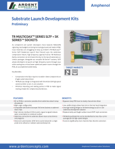
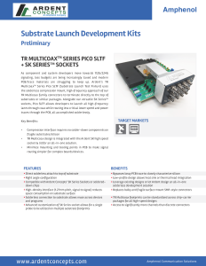
As component and system developers move towards 112G/224G signaling, loss budgets are being increasingly taxed and modern PCB/trace materials are struggling to keep up. Ardent’s TR Multicoax™ Series SLTF (Substrate Launch Test Fixture) uses the solderless compression mount, high-frequency approach of our TR Multicoax family connectors to terminate directly to the top of substrates or similar packages. Alongside our versatile SK Series™ sockets, SLTF allows developers to launch all high-frequency lanes through coax while routing less critical lower speed and power traces through the PCB, all accomplished solderlessly.
Applications
- 112/224 Gbps SerDes characterization
- Co-packaged connector testing
- DDR memory testing
- 5G (e.g.NR FT2)
Features and Benefits
- DC to 70 GHz+ connector provides direct solderless attach to top of substrate, bypassing lossy PCB trace to closely characterize silicon
- Right angle configuration allows heat sink or thermal head integration
- Compatible with Ardent Concepts’ SK Series Sockets or soldered-down chips encouraging reuse of existing designs (or let Ardent design an all-in-one solderless development solution)
- High-density interface (2.54mm pitch, signal to signal) reduces space consumption on substrate surface and replaces bulky, fragile surface mount SMP-style connectors
- Solderless connection to substrate allows reuse across devices and programs
- Advanced customization of SK Series socket allows for a single probe to be utilized on multiple substrate footprints, providing access to significantly more channels than discrete connectors
Solderless Technology
The Art of TR Multicoax
Ardent’s TR Multicoax series represents a significant advancement in connector technology, with its solderless approach via a PCB footprint. This innovation allows for seamless signal and ground connections directly on the PCB, bypassing the need for soldering which can introduce variability and reliability concerns. The footprint design, optimized for high-performance applications, supports frequencies up to 90 GHz, with options for further launch optimization to meet specific program requirements. This approach simplifies the PCB design process, enhances signal integrity, and facilitates easy reconfiguration for future design iterations.
Features and Benefits
- Solderless Connection: Direct compression mount to PCB ensures reliable signal integrity without the inconsistencies of soldering.
- Optimized for High Frequencies: Footprints support frequencies up to 70 GHz, with services available for higher frequency optimizations, addressing the needs of advanced applications.
- Versatile Plating Options: Supports various noble metal plating options like hard gold over nickel, ENIG, and ENIPIG, offering flexibility in design and fabrication.
- Detailed Optimization Services: Ardent offers detailed footprint optimization services based on specific PCB stack-ups, enhancing performance tailored to each customer's unique requirements.
- Easy Implementation: Comprehensive guidelines and optimization reports provided by Ardent facilitate easy adoption and integration into PCB designs.
- Reusability Across Designs: The dense footprint not only saves space but is designed to be reusable across different programs, maximizing cost efficiency.
Field Replaceable Interface
Applications
- Easy Replacement: The TR Multicoax interface can be easily removed and replaced at the customer site, minimizing downtime and ensuring continued high performance.
- Superior Signal Integrity: Designed with precision, the interface maintains exceptional signal integrity, crucial for high-frequency applications. Replacement interfaces offer the same performance as new products.
- Durable and Reliable: Built to withstand rigorous use, our interfaces are made with high-quality materials that ensure long-lasting performance. While our interfaces are extremely robust, suitable for cryogenic and space applications, in the rare event of damage, the replaceability offers an easy and effective maintenance option.
Description
Our TR Multicoax Series features an innovative field replaceable interface, designed to provide superior performance and ease of maintenance. This advanced interface ensures that your high-frequency connections remain reliable and efficient, even in the most demanding environments.
Mechanical Reliability
- The TR Multicoax series connectors excel in demanding environments like commercial satellites, quantum computing, and automated test equipment. Built with advanced materials, they ensure durability and reliability, maintaining performance even in temperatures as low as millikelvin.
- Meeting Mil-Std and NASA/ESA standards, these connectors provide consistent, reliable connections crucial for signal integrity engineering. Rated for up to 1000 mechanical cycles, their precision and durability guarantee long-term performance, preserving signal integrity and minimizing measurement variability.
- Access our comprehensive test reports for detailed technical validation. Contact us to enhance your projects with the TR Multicoax series' reliable, high-performance connectivity.
Form Factors
SLTF
| Specification | Value |
|---|---|
| Insertion Loss | <3 dB at 67 GHz |
| Return Loss | < -20 dB to 28 GHz; < -17 dB to 67 GHz |
| Interface Impedance | 50Ω ± 5% SE; 100Ω ± 5% Diff. @ 14 ps R.T. |
| Interface Crosstalk | < -70 dB to 67GHz |
| Phase Matching | ±2ps (±1ps available) between all cables in unit |
| Connector Specification | SMA, SMK (2.92mm) or V (1.85mm) |
| NOTE: Data obtained from de-embedded measurements of the probe. Includes 1.85mm connector, ~3” of 0.047” cable, and compression pin interface mated to perfect 50Ω test fixture. Connector-to-substrate transition effects not captured in measurement. | |
| Specification | Value |
|---|---|
| Channel Count | 16, 18 |
| Signal Pitch | 2.54mm row, 3.0mm column |
| Cable Type | 0.047” Flexible Coax |
| Cable Length (in inches) | 3, 6, 9, 12, 18, 24 |
| Mounting | 4x #2-56 hex-head screws |
| Mating Life | 1,000 mechanical cycles (1 cycle = 1 mate & 1 demate) |
| Compression Force at Interface | 180g per channel |
| Temperature Rating | -55°C to ° 125°C |
| NOTE: Temperature range for mechanical integrity only. S-parameter specs validated at 20°C | |
pico-SLTF
| Specification | Value |
|---|---|
| Insertion Loss | ≥ -0.34 * √(f) dB to 67 GHz (f in GHz) |
| Return Loss | < -18 dB to 56 GHz; < -14 dB to 67 GHz |
| Interface Impedance | 50Ω ± 5% SE; 100Ω ± 5% Diff. @ 14 ps R.T. |
| Intra-pair Crosstalk | < -40 dB to 67 GHz |
| Phase Matching (relative to block) | ±2 ps standard, ±1 ps premium |
| Connector Specification | 1.85mm (Female) |
| NOTE: Data obtained from de-embedded measurements of the probe. Includes 1.85mm connector, ~3” of 0.034” cable, and compression pin interface mated to perfect 50Ω test fixture. Connector-to-substrate transition effects not captured in measurement. | |
| Specification | Value |
|---|---|
| Channel Count | 6 pairs; 12 SE channels |
| Pitch | 1.27mm intra-pair |
| Mounting | Screw Mount; 4x M2 Hex screws |
| Mating Life | 1,000 mechanical cycles (1 cycle = 1 mate & 1 demate) |
| Compression Force at Interface | 20g per pin |
| Temperature Rating | -55°C to ° 125°C |
| NOTE: Temperature range for mechanical integrity only. S-parameter specs validated at 20°C | |
Technical Information
Contact Factory
"*" indicates required fields